Network Topology
Network Topology
This section covers how to build the routing and switching topology for your network. Your needs will vary considerably based on the specifics of your network so if you’re not familiar with all of these concepts you may need to do some outside research (or ask in the chatroom).
Getting lost in the interwebs?
Outpost Plus is the organization behind startyourownisp.com. We understand that network configuration is sometimes best left for professionals, and our professional network engineers are here to help! Contact us to discuss your project.
Terminology
These are terms that will come up while discussing network topology. If you are entirely unfamiliar with these terms you might want to start with some background reading.
- Router - A device that sends packets to different destinations based on the packet’s destination IP address and the router’s routing table.
- Public IP Addresses (v4 and v6) - An Internet address that is routable on the public Internet. All devices need to have a public Internet address in order to communicate on the Internet, and all addresses must be unique.
- Private IP Addresses - Any of a set of IP addresses that are set aside to be used in private networks. These addresses can only be used on private/internal networks, not the Internet.
- NAT - Network Address Translation. Allows devices that are using private IP Addresses get on to the Internet by sharing a Public IP Address.
- Network Switch - A device that sends packets to different destinations based on the packet’s destination MAC address and the switch’s bridge table.
- DHCP - Dynamic Host Control Protocol. A service that provides IP Addresses and DNS configuration for the devices on the network so they don’t have to be configured manually.
- VLAN - Virtual LAN. Allows multiple logical LANs to co-exist on the same switching hardware.
Gotta Start Somewhere
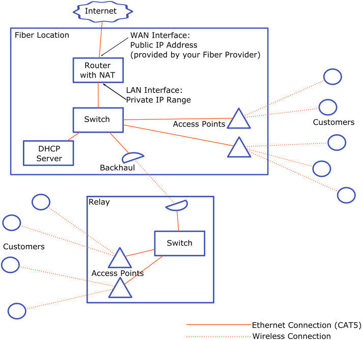
The easiest, most straightforward network configuration resembles what you probably have in your network at home - a router with 1 public IPv4 address and all of the devices connected to it using private IP addresses and NAT to get to the Internet.
This configuration isn’t very scaleable due to having all of your customers on the same broadcast domain and sharing the same IP address, but it’s an OK place to start.

Making it Scaleable: Reduce NAT
With the above configuration all of your customers are sharing a single IP address. This means that if one of them gets the IP address blocked from a service (for sending spam, for example) then it’s blocked for everyone. Ideally you would give each customer their own IP address but there aren’t really any more IPv4 addresses available.
If you can get more than one IPv4 address from your Fiber provider then go for it - you can configure your NAT to use a pool of IP addresses rather than just one, which is a little better.
You can also try to push your customer’s traffic to IPv6 as much as possible. IPv6 addresses are easy to come by and most equipment and many current web services support IPv6.
Segment Broadcast Domains
During normal network operation all devices on the network emit ‘broadcast’ packets - packets that are sent to all other nodes on the same broadcast domain. With the above configuration all of your customers are on the same broadcast domain, meaning that all of those packets will go to all of the customers and will quickly slow down the network. To avoid network congestion you’ll want to split your customers up into multiple broadcast domains.
Adding routers or using VLANs are both ways to break up your broadcast domains. Both are explained below.
Adding routers
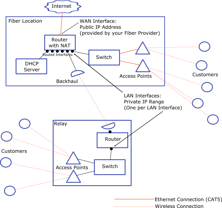
Adding a router at each tower allows you segment broadcast domains to a single tower or even a single access point. Each tower can have it’s own routed interface with the default route in the router pointing at the upstream relay’s router.
Pros:
- Routing tables can be configured automatically using a routing protocol (like OSPF)
- Network can more easily support redundant backhaul links
Cons:
- Routers add more latency than switches
- DHCP Configuration is more complicated
- Routers are more expensive than switches (for the same performance)
- Getting your routing protocol config right can be tricky, and not using one means lots of manual configuration

VLANs
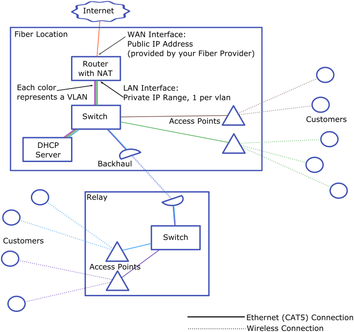
A VLAN segmented network will use a switch at each tower rather than a router. A VLAN can be built from each access point all the way to the core of the network. This allows each tower or even each access point to be on it’s own routed interface with the router at the core of the network.
Pros:
- Lower latency across the network
- Less expensive
- Easier DHCP configuration
Cons:
- Requires more careful Spanning Tree Protocol configuration to avoid switching loops
- More difficult to add backhaul redundancy

Enforcing Speed Packages
You will probably be selling your service with an associated speed package - say 30, 50 or 100Mbps. If you find that some customers are consistently using more than what they’re paying for then you’ll want to limit their max throughput so they don’t slow other customers down.
The easiest way to start doing this is to set limits in the CPE radio on their roof. All modern WISP equipment will allow you to configure the max throughput for download and upload speeds.
As your network grows you can automate the process of limiting customer’s speeds rather than managing them manually. Some billing systems, such as PowerCODE, will do most of this for you.